Planning
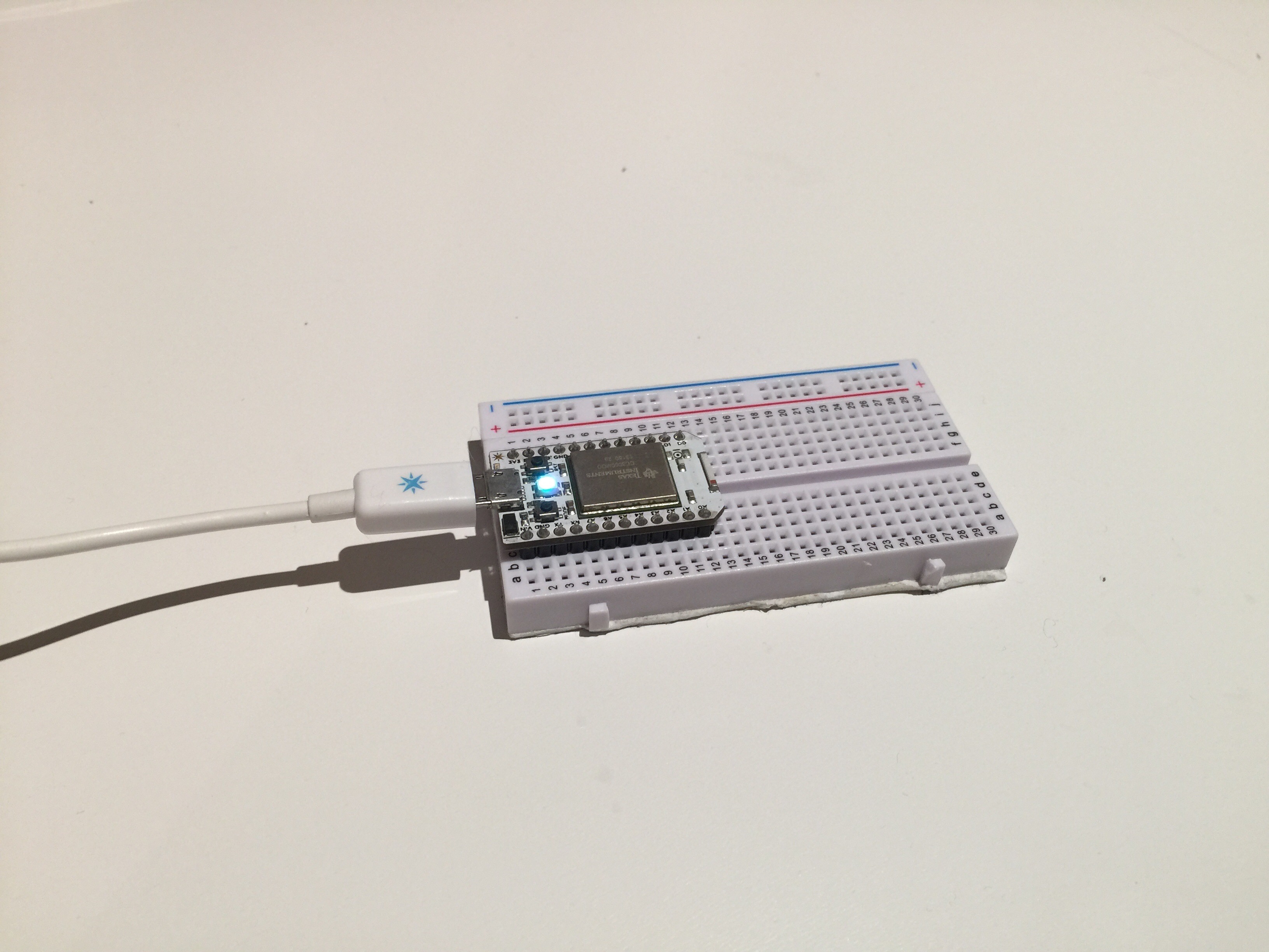 This is the Core. A wifi-enabled micro-controller board the size of a postage stamp. Particle, the producer of the board is an awesome company that I have been a fan of since I backed them on Kickstarter. I received the my core in 2013 but didn’t actually begin to use it until early 2014.
 In this picture, my Core has two buttons hooked up to it. This simple circuit allowed me to post a tweet whenever I pressed one of the buttons. This little project allowed me to make use of API’s to sent data directly from the core to Twitter.
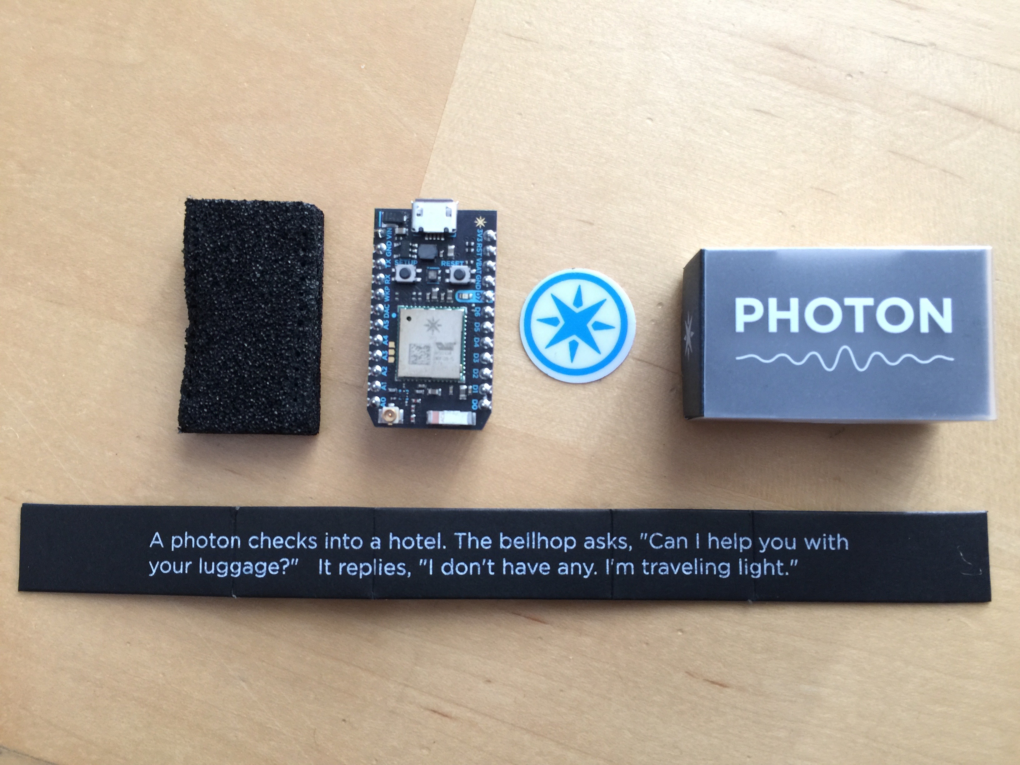 In late 2014 Particle developed a new IoT board. It was called the Photon and included many upgrades including faster wi-fi, more storage and a cheaper price. I pre-ordered a few, and waited months for them to arrive. Eventually in July 2015, my Photons came and I officially started my project.
 I wanted to create a PCB for my product to hold it all to together and for it to look well made. I decided to use Fritzing, a free to use program that allows you design PCBs by dragging and connecting components together on virtual PCB. Here is the first board that I actually paid to have made. I immediately noticed that the it was faulty because I had an error in my design.
 I actually bothered to assemble this version of the board, as I couldn’t immediately spot any flaws with it. The board featured three servo motor ports, an RGB port, a microphone port, two button ports, a buzzer port and a GPIO header. However there was a conflict with the pins, as the RGB was not connected to PWM pins on the Photon, meaning that the brightness of the LEDs could not be changed dynamically. Also the servos did not function. I didn’t know it yet, but this was because there was not enough power on the Photon to drive three motors.
 Side note, the PCB fabrication house that I had been ordering my boards from only sold boards in multiples of three, so I had to buy three times as many boards as I needed. The fabrication house was in America, which meant two things. It took weeks to ship and the shipping cost more than the boards.
 After fixing many of my mistakes with my last board, I quickly ordered a replacement. This new board corrected the mistakes I had with my previous boards, but it still was not perfect, as the motors did not function properly when the RGB was in use because of a limitation of the Photon. The are two pairs of PWM pins that share the same clock, meaning that they can not both be used as PWM outputs at the same time.
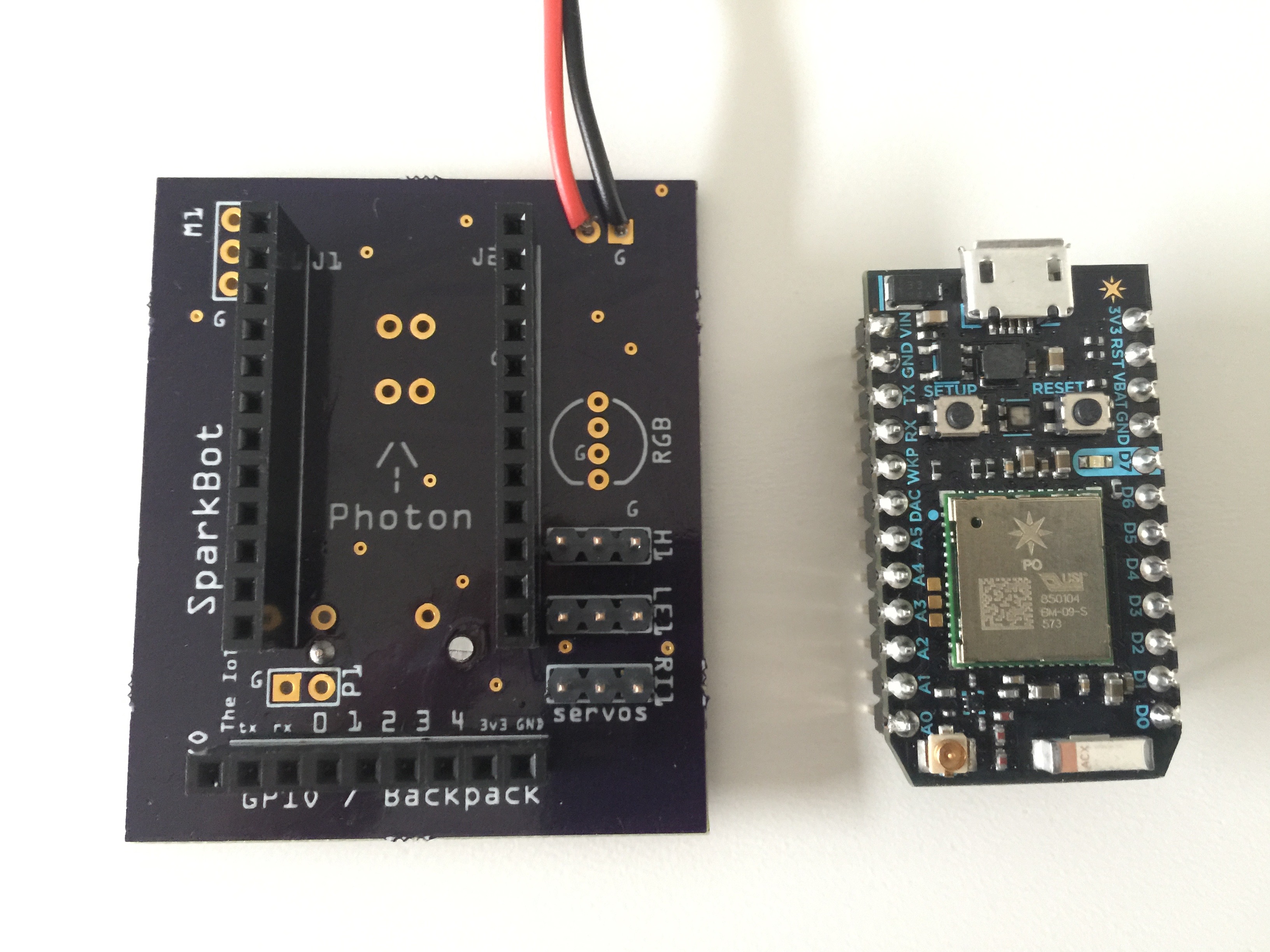
 In this third revision of the board, the RGB and buzzer worked, the GPIO worked and the buttons worked. The servos were non-functional, despite the fact that this update was supposed to fix the servos. I also found a new fabrication house based in the UK that offered pretty fair prices and didn’t require me to buy my board in multiples of three. I assembled this board in November.
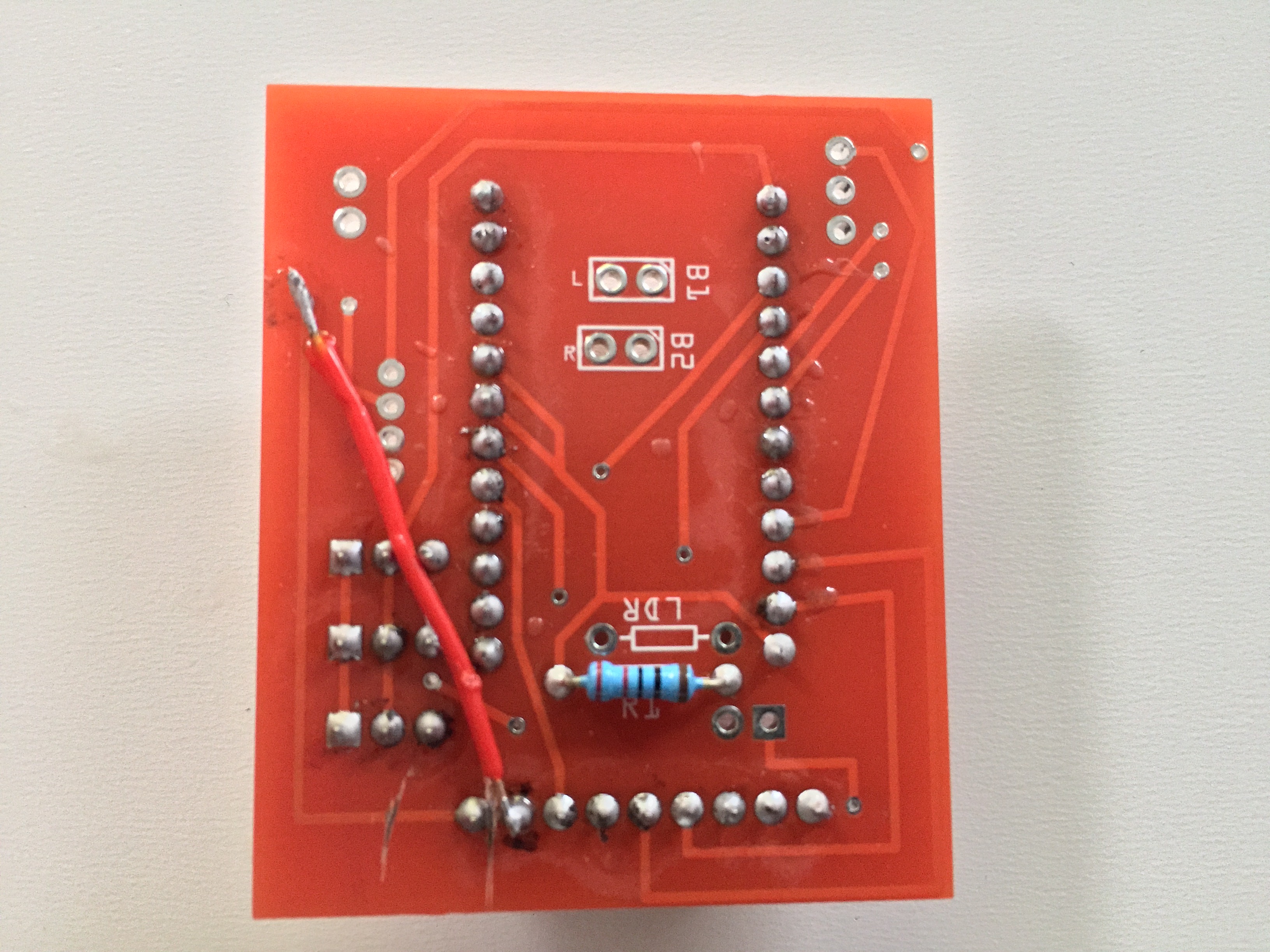 There was in fact a mistake in this board. On the bottom there was an overlapping wire that I had to cut at two points and solder some scrap wire across the board to replace that wire. This wire covered up the RGB port on the PCB. Additionally, the microphone port on the board was wired backwards because the part in Fritzing was incorrect.
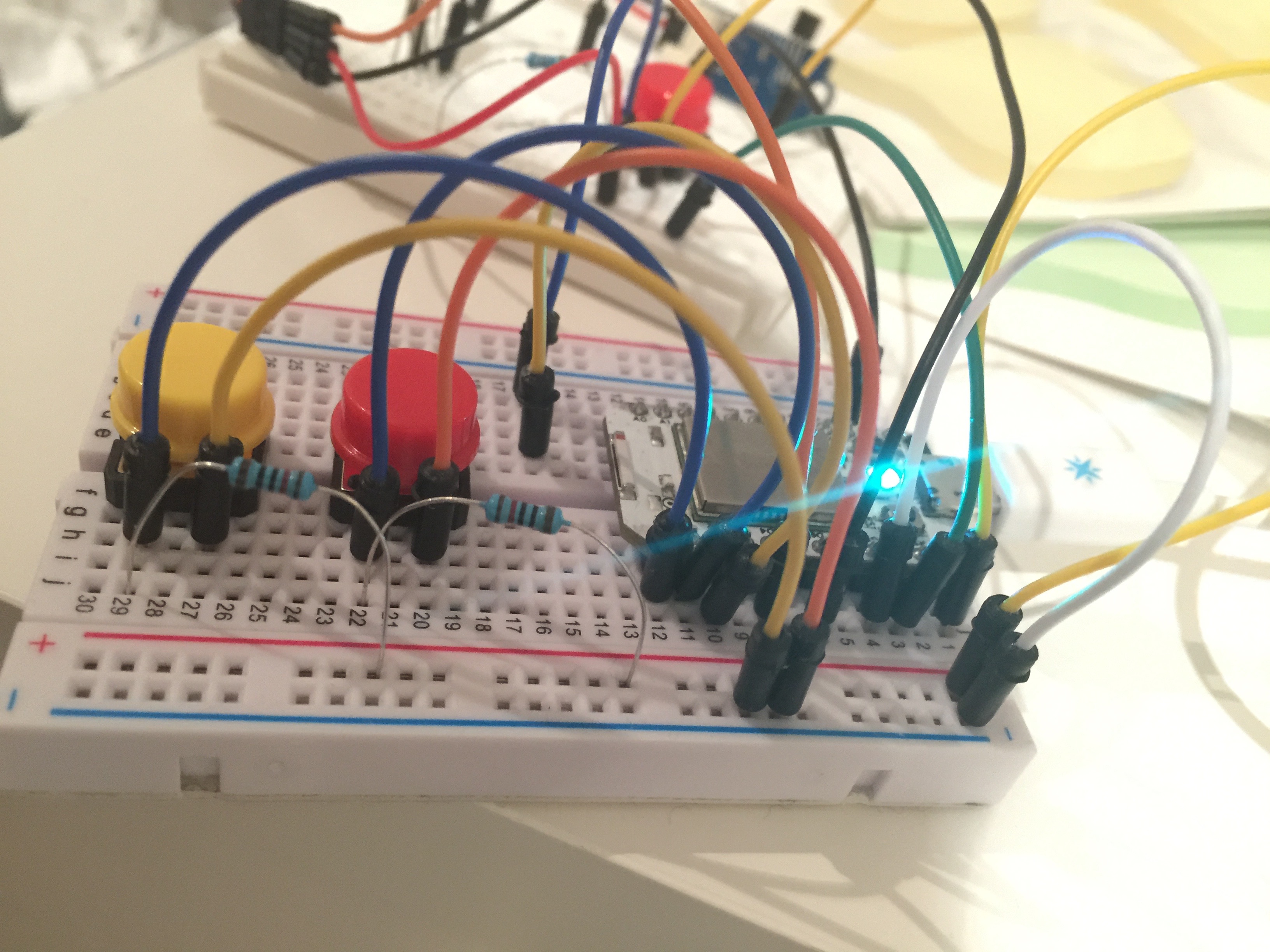
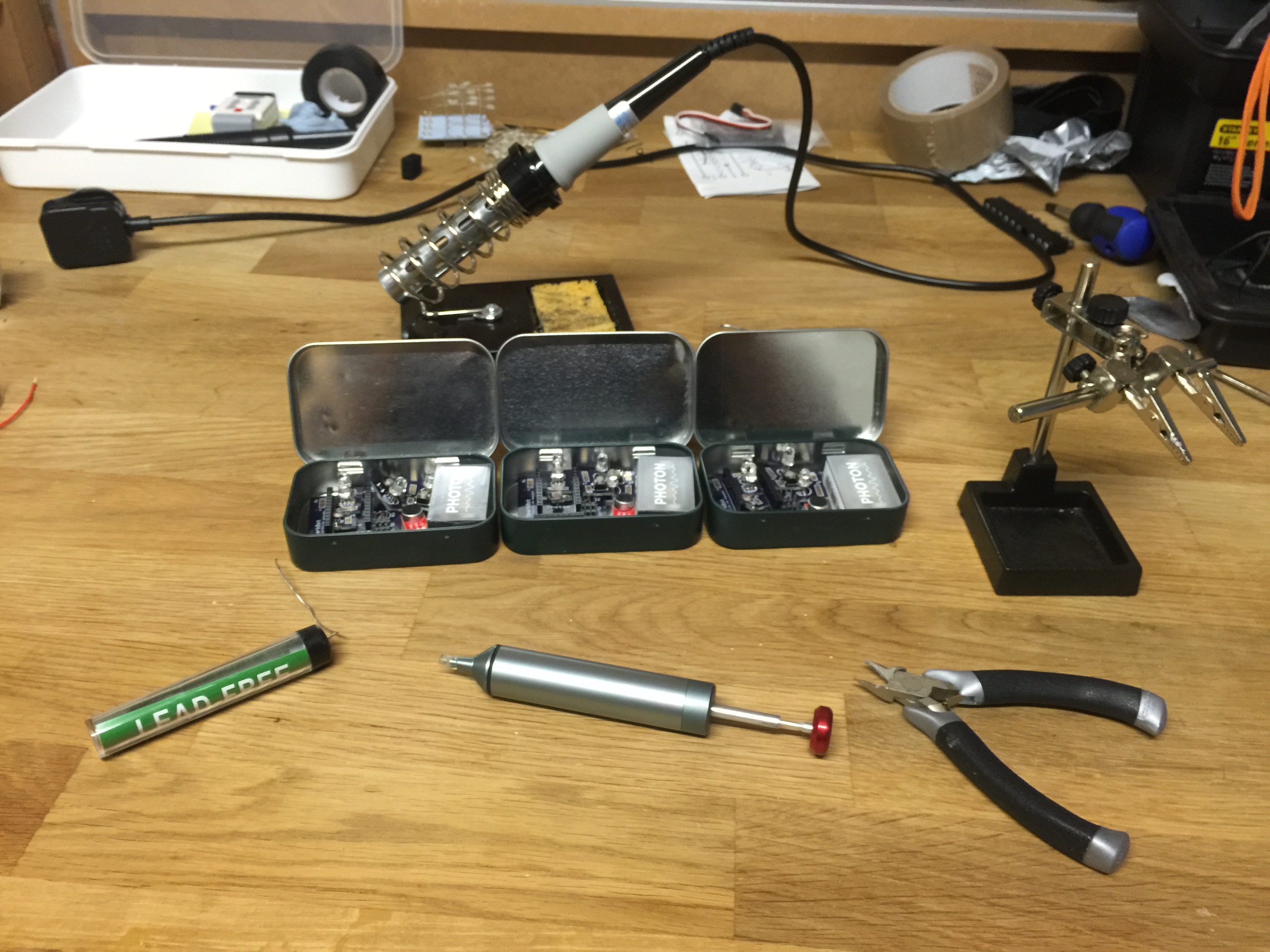
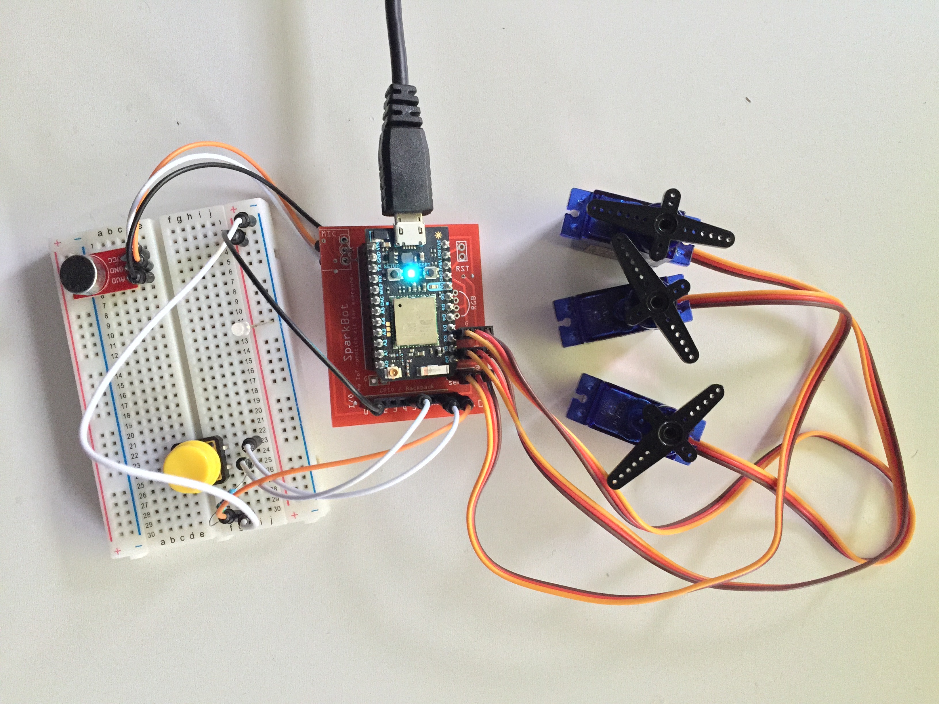 Here is a picture of my project with the 3.0 board. I had to use a bread board because the microphone was backwards and because I didn’t want to have to solder any additional parts to this board because I knew I needed to order a replacement.
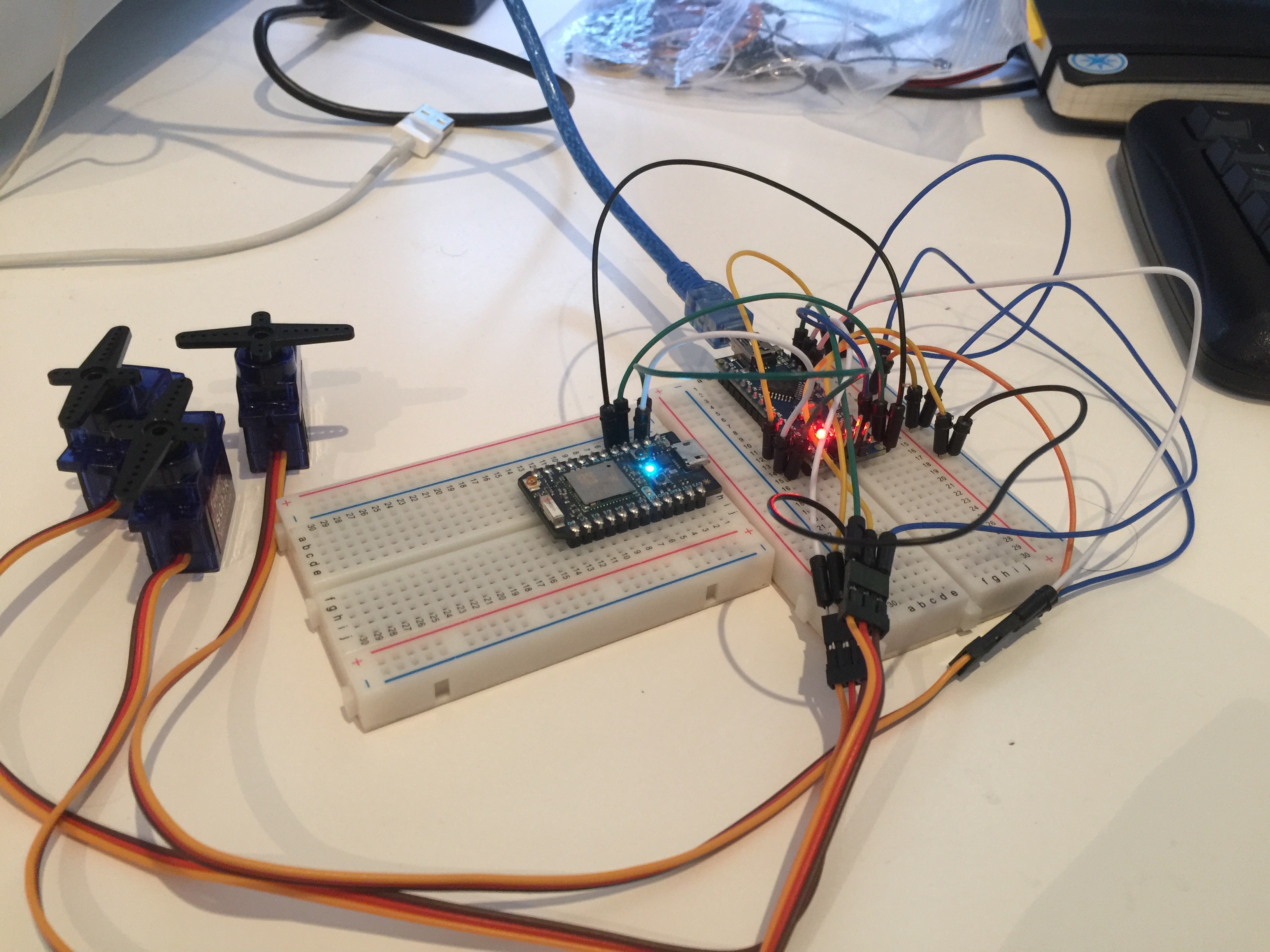 Here is the breadboard prototype of my board.
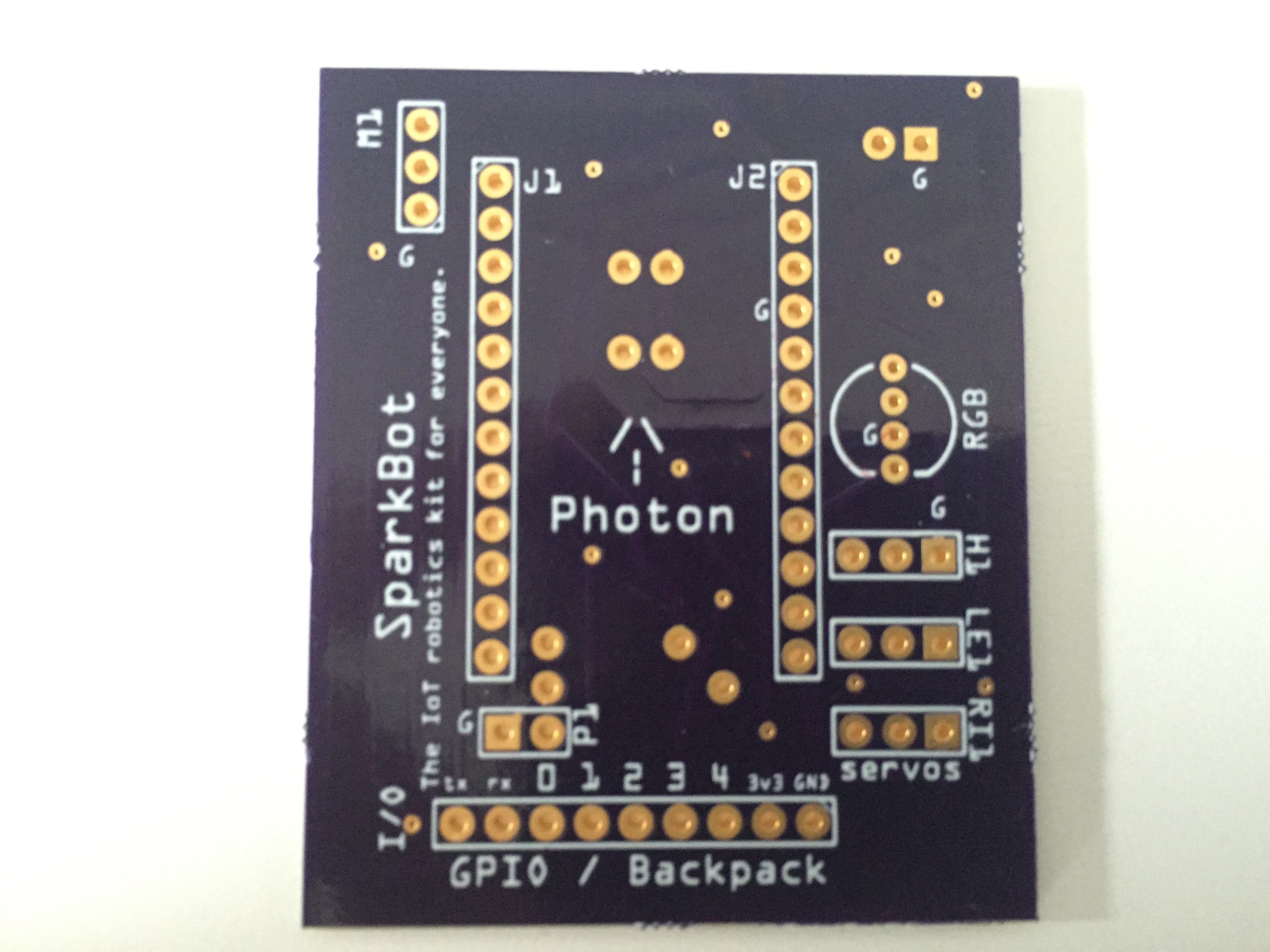
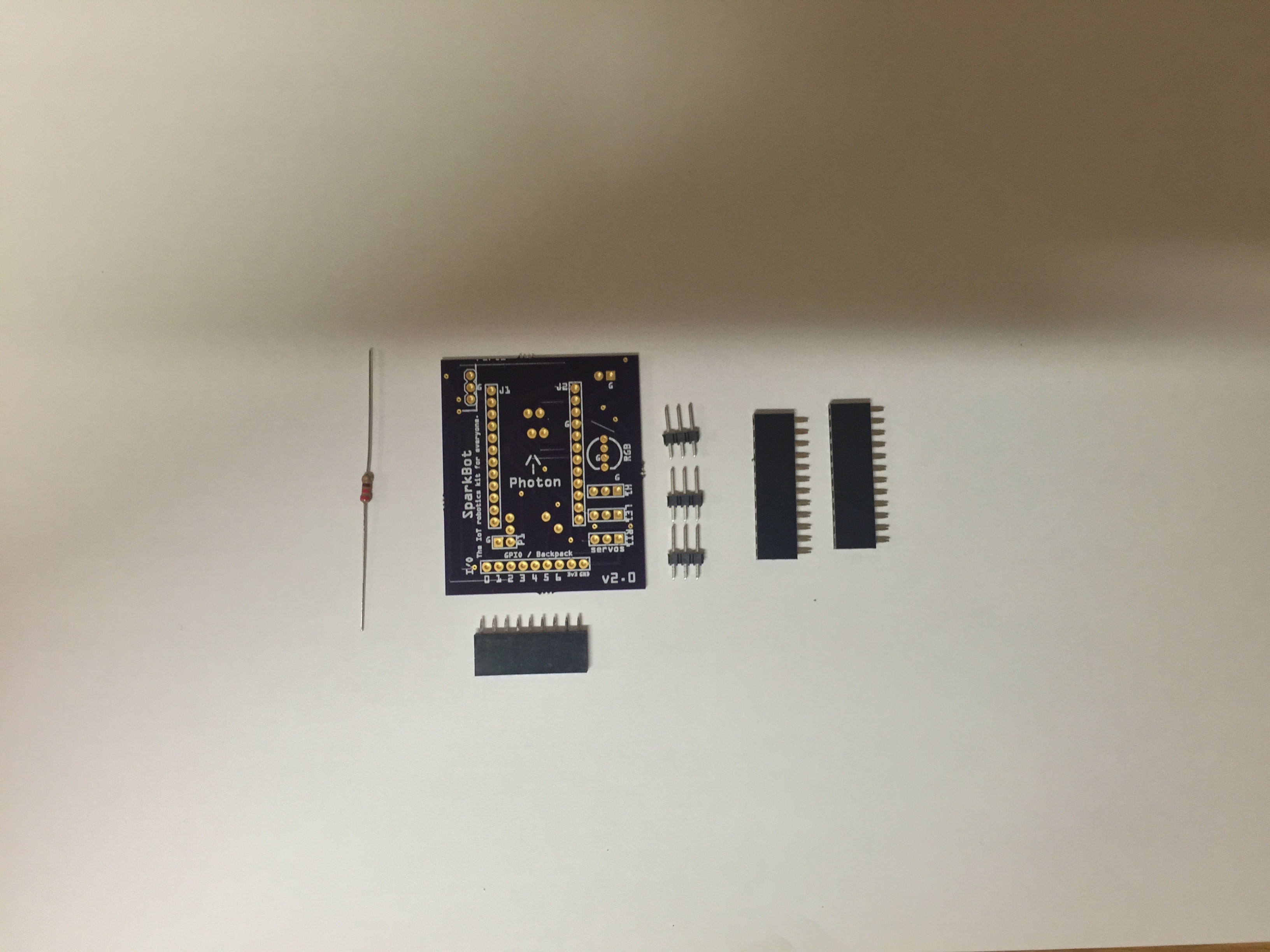
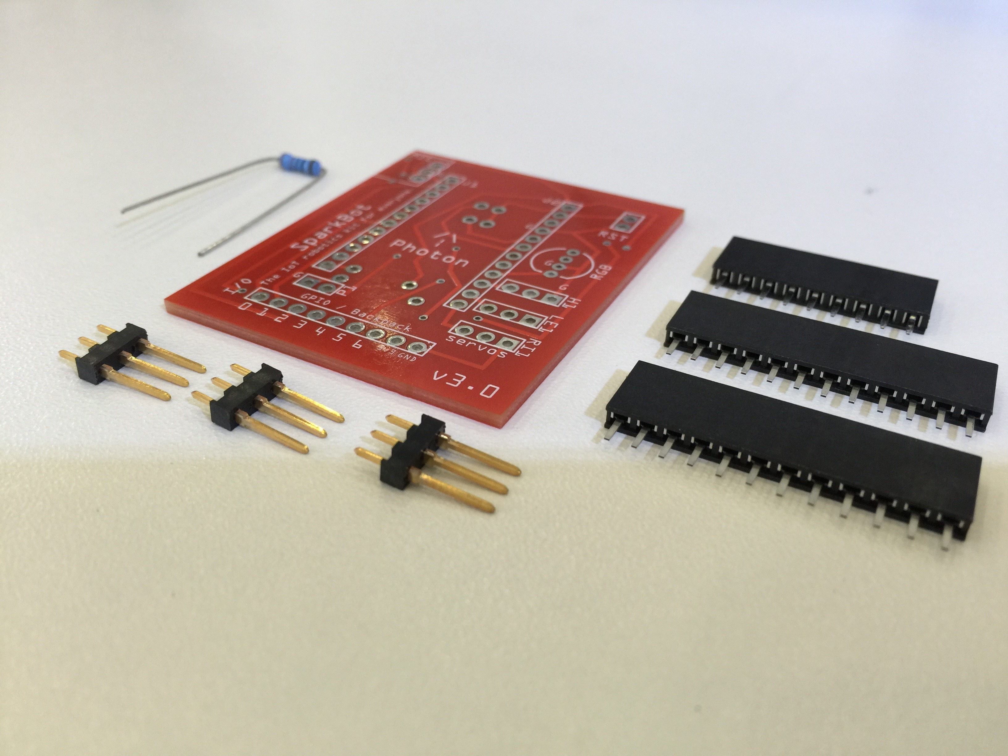
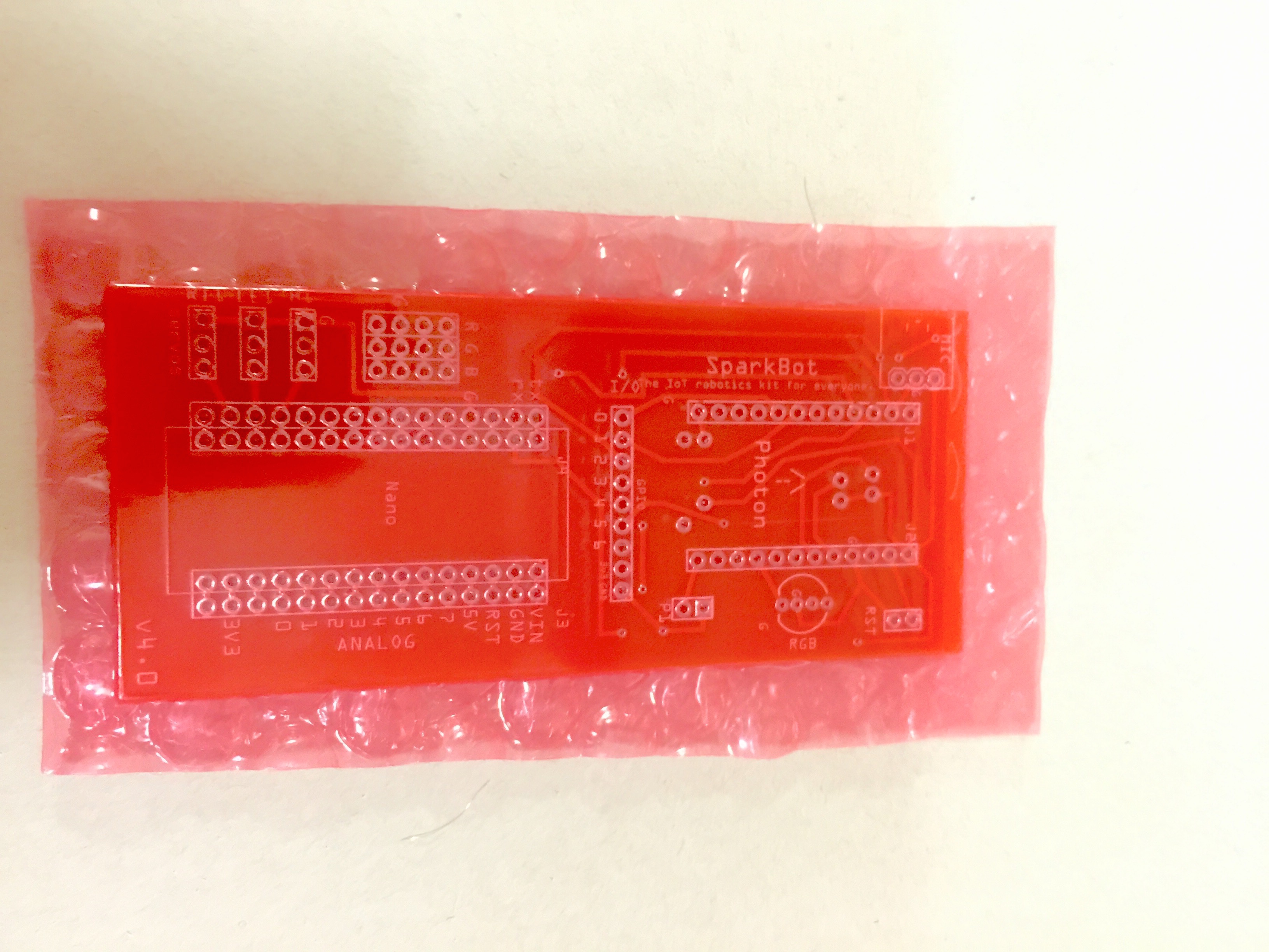 Here is a picture of my final PCB that came in February. I decided to make my board longer so that it could have an additional micro-controller board, an Arduino nano, to control the motors and lights in my product. This board does not have any errors because I checked my design many times before ordering it.
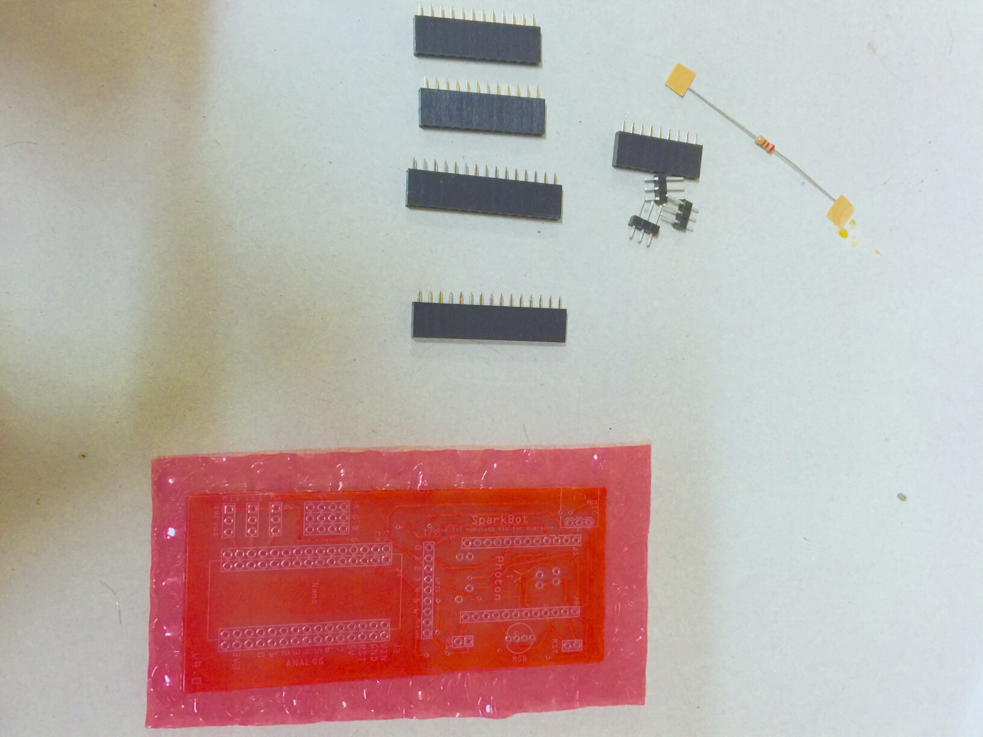 Assembling my boards wasn’t very difficult. I just had to put the components in the holes in my PCB and solder them in. I took this picture of my board and components right before assembling my product.
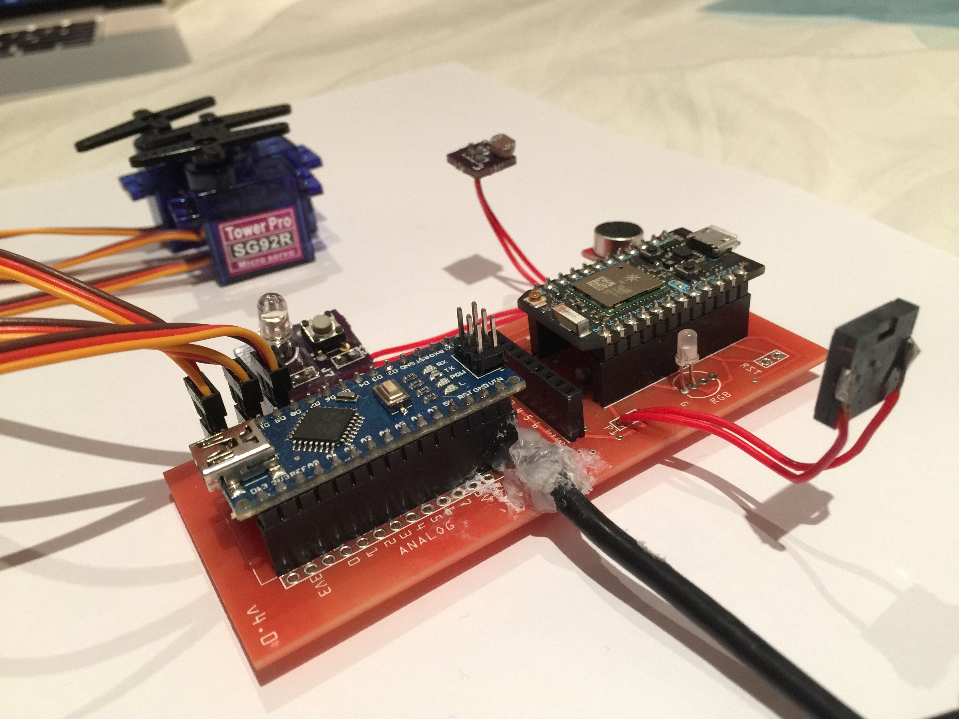 Here is a close up of my assembled product. All of the basic components in the previous image have been soldered onto the board, and I have soldered on the microphone, buzzer, photoresistor, LED, and RGB button board onto my product, and I have also plugged in the servos and inserted my Photon and Arduino Nano. That nasty hot glue mess you see is my attempt at creating a power connector for my product.
Rubric
| 0-1 | 2-3 | 4-5 | 6-7 |
| Explains some steps to be taken with limited details. Creates no timeline and shows no attempt to describe the skills, qualities, and/or values involved in the project. Describes some outcomes of each step using irrelevant or no evidence |
Explains most steps to be taken. Creates a basic timeline and shows a limited attempt to describe the skills, qualities, and/or values involved in the project. Uses limited or irrelevant evidence to outline most of the outcomes of each step of the process. |
Explains all steps to be taken. Creates a developing timeline and lists the skills/qualities involved at each point in the process. Uses relevant evidence, examples, and criteria for success to describe all outcomes of each step. |
Explains several/varied clear steps to be taken in their process. Creates a detailed and complete timeline and outlines the skills/qualities involved at each point in the process. Uses a variety of relevant evidence, examples, and/or success criteria explain several/varied outcomes of each step. |